The caliche layers beneath North Las Vegas create a distinct challenge for any subsurface investigation. These hard, cemented carbonate zones scatter signal and mask deeper strata. Our resistivity / VES surveys cut through this noise. We use expanded arrays and DC current injection to map contrasts that standard borings might miss. The method works well in the arid Mojave environment, where dry surface soils demand high-contact-resistance mitigation. For projects near the Las Vegas Wash or the northern edge of the city’s alluvial fan, we often pair VES with seismic refraction to cross-validate interpreted bedrock depth, and with CPT testing when soft clay lenses are suspected beneath the caliche cap.
Dry caliche caps in North Las Vegas require tailored array lengths to punch through the resistive crust and image the saturated zone beneath.
Site-specific factors
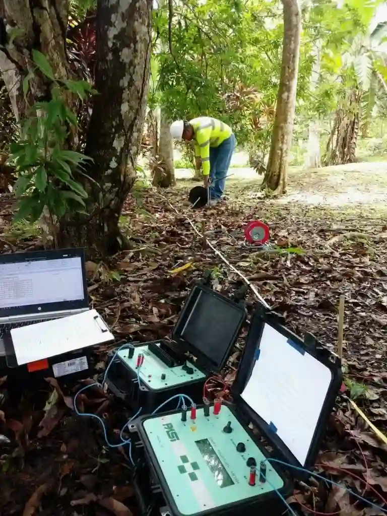
The field setup uses a heavy-duty transmitter coupled to a multi-electrode spread across the survey line. In the compacted desert pavements common on North Las Vegas lots, achieving low electrode contact resistance is the first battle. We saturate each stake point with a saline solution and, when necessary, use short pilot holes to penetrate the duricrust. Skipping this step leads to noisy data and wasted line kilometers. A secondary risk is cultural interference: buried utilities, reinforced concrete pads, and nearby power lines distort the electric field. Our crew maps all surface infrastructure before laying out the array, and we apply notch filters during post-processing to strip 60 Hz noise. Without these precautions, a VES profile can misrepresent a utility trench as a low-resistivity aquifer, triggering unnecessary redesign.
Common questions
How deep can a VES survey investigate in North Las Vegas soils?
With a 300-meter maximum electrode spread, we routinely image to 120–150 meters depth. The practical limit depends on the resistivity contrast. High-resistivity caliche caps require longer spreads to push current deeper. We adjust the array geometry after reviewing any available boring logs from the site.
What is the typical cost for an electrical resistivity survey here?
Most North Las Vegas VES surveys run between US$680 and US$1,000. The final figure depends on the number of soundings, the maximum electrode spread required, and site access conditions. We provide a fixed-price proposal after reviewing your project location and objectives.
Can you run resistivity lines on paved surfaces?
Yes, but with limitations. We use drilled contact points through asphalt or concrete to reach native soil. This adds time per station. Large continuous slabs with heavy rebar create a conductive short circuit that masks deeper signals. We map slab extent first and offset lines where possible. In parking lots, we often combine VES with MASW to separate pavement effects from true stratigraphy.
How do you calibrate resistivity data in North Las Vegas?
The reference range for this service in North Las Vegas is US$680 - US$1.000. The final price depends on the project scope and volume.