← Home · Geophysics

Seismic Tomography (Refraction/Reflection) in North Las Vegas

Together, we solve the challenges of tomorrow.

LEARN MORE →

The contrast between North Las Vegas neighborhoods tells a subsurface story you can feel under a dozer blade. Up near Aliante, fresh alluvial fans from the Sheep Range hide shallow caliche lenses that ring like a bell under seismic impact. Down south toward the industrial corridor around Cheyenne Avenue, older basin-fill deposits interbed with fine-grained clays from ancient Lake Mojave. That shift means the same foundation approach won't work in both zones. We run seismic tomography—refraction for mapping top-of-bedrock and rippability, reflection for deeper structure—to give structural engineers a velocity model they can trust. When the data shows a jump from 800 m/s to 2,400 m/s over ten vertical feet, you know exactly where excavation changes character. Pairing these results with a CPT test on the fine-grained side of the basin gives us a continuous profile that validates the tomographic inversion. The City of North Las Vegas sits in Clark County's Seismic Design Category D, so getting the shear-wave velocity right is not academic—it's what keeps a tilt-up warehouse from racking during a moderate event.

A 2D velocity cross-section turns a guess about bedrock depth into a contour you can stake on the ground.

Our approach and scope

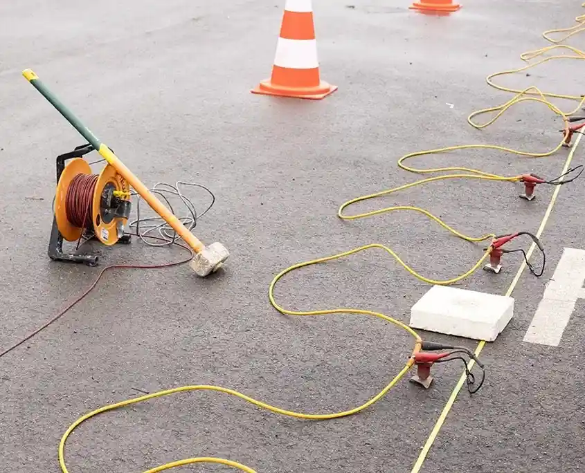
North Las Vegas sits at an average elevation of 2,200 feet, but the depth to competent caliche or cemented paleosol can swing from three feet to over forty across a single parcel. That's where seismic tomography earns its keep. We lay out a 24- or 48-channel spread with 4.5 Hz geophones, hit it with a sledgehammer or an accelerated weight drop, and invert the first arrivals into a 2D P-wave velocity cross-section. The method resolves layers with velocity contrasts as low as 15%, so it picks up weathered versus intact caliche—a distinction that governs drilled pier socket depths under IBC Chapter 18. For deeper targets—fault strands that may offset the Las Vegas Valley Shear Zone—we switch to a reflection acquisition with tighter station spacing and a higher-energy source. A MASW survey run along the same line extracts Vs directly, which feeds the site classification per ASCE 7-22 Table 20.3-1. When you need to know whether that low-velocity zone at 60 feet is a paleochannel or a liquefiable lens, combining the P-wave tomogram with the liquefaction assessment gives you a defensible answer. The output is a raster or vector velocity model that goes straight into PLAXIS or FLAC3D for soil-structure interaction.
Seismic Tomography (Refraction/Reflection) in North Las Vegas
Technical reference image — North Las Vegas

Site-specific factors

The mistake we see too often in North Las Vegas is treating a single borehole as representative of a ten-acre site and skipping geophysics entirely. Caliche in the Las Vegas basin is discontinuous—it pinches out, it fractures, it grades laterally into loose carbonate dust. Drill through a window of soft material and you'll log refusal at 50 feet. Move 200 feet west and you hit hardpan at 8 feet. If the structural design assumes uniform bearing based on that one log, you get differential settlement that shows up as drywall cracks before the certificate of occupancy is six months old. Seismic refraction tomography catches that lateral velocity gradient and maps the caliche roof continuously, so the foundation engineer can specify variable pier lengths or a post-tensioned slab where the transition zone runs diagonally under the building footprint. The alternative—discovering the variability during excavation—costs change orders and kills schedules.

Need a geotechnical assessment?

Reply within 24h.

Email: info@geotechnicalengineering1.com

Video overview

Technical data

ParameterTypical value
Source type8 kg sledgehammer / 250 kg AWD (refraction); 12-gauge Betsy gun or 2 kg explosives (reflection)
Geophone frequency4.5 Hz vertical-component (refraction); 14 Hz or 28 Hz (reflection)
Spread configuration24–48 channels, 2–5 m spacing; end-on or split-spread
Depth of investigationTypically 15–30 m (refraction); 20–120 m (reflection, source-dependent)
Inversion methodTomographic (wavepath eikonal) or delay-time; reflection stack with CMP binning
Output2D P-wave velocity model (SEG-Y + ASCII xyz), ray coverage plot, RMS misfit
Vs30 derivationVia MASW on same line or correlation from P-wave lithology constraints
Reporting standardIBC 2024 Section 1613, ASCE 7-22 Chapter 20, ASTM D5777-18

Complementary services

01

Refraction micro-tomography for foundation design

High-resolution 2D P-wave profiling with 1–2 m station spacing to map top-of-caliche, rippability, and lateral velocity variations across building pads. Delivered as SEG-Y files plus an interpreted depth-to-competent layer map keyed to IBC Site Class boundaries.

02

Deep reflection profiling for fault and basin structure

Multi-fold seismic reflection acquisition targeting 30–200 m depth range. Used to image Quaternary fault strands within the Las Vegas Valley Shear Zone and to delineate the bedrock-basin contact where refraction energy won't penetrate the velocity inversion.

Standards used

IBC 2024 Section 1613 (Earthquake Loads – Site Class Determination), ASCE 7-22 Chapter 20 (Site Classification Procedure), ASTM D5777-18 (Standard Guide for Using the Seismic Refraction Method), ASTM D7128-18 (Standard Guide for Using the Seismic Reflection Method), ASTM D7400-19 (Standard Test Methods for Downhole Seismic Testing)

Common questions

How deep can seismic refraction see in North Las Vegas caliche?

With a 48-channel spread at 5 m spacing and a 250 kg accelerated weight drop, we routinely image to 30–40 m depth in cemented caliche. The limiting factor is the velocity inversion—if a soft layer underlies a hard one, refraction won't see below it. In those cases we switch to reflection or pair the line with MASW to recover the full velocity profile.

What is the cost range for a seismic tomography survey on a half-acre commercial lot?

For a typical half-acre lot in North Las Vegas with two 48-channel refraction lines and one reflection line, the survey package runs between US$2,960 and US$4,530 depending on source type, line length, and whether we run concurrent MASW for Vs30. A formal proposal follows a site walk and review of the boring logs.

Can you shoot lines on asphalt or concrete?

Yes. We plant geophones through pre-drilled 3/8-inch pilot holes in pavement and couple them with sand or bentonite. The source impact is delivered via a steel strike plate on asphalt or directly on exposed soil. We have shot dozens of lines in the North Las Vegas industrial parks without damaging existing hardstand.

What deliverables do we get and how fast?

You receive a raw SEG-Y file, a processed ASCII xyz velocity grid, the ray coverage plot, and a PDF report with interpreted depth sections tied to any available borehole control. Turnaround is typically five to seven business days after field acquisition ends.

How does the shear-wave velocity from tomography compare to downhole testing?

Refraction tomography gives you P-wave velocity directly. To get Vs we either run a parallel MASW spread or cross-correlate the P-wave model with lithology from a borehole to estimate Vs using published empirical relationships for Las Vegas basin sediments. For critical Class D or E sites, we recommend a downhole seismic test per ASTM D7400 to calibrate the geophysical model.
Location and service area

We serve projects in North Las Vegas and surrounding areas.

View larger map